Aging water systems face a number of challenges, including a growing and urbanizing population, water scarcity and more extreme weather events, an aging workforce, and increasing expectations from customers.
For reasons such as these, water utilities worldwide are moving to more advanced operational management solutions using the Internet of Things (IoT). These IoT devices can provide valuable insight into the operational efficiency of a water system and give utility operators the analysis and intelligence necessary to help make informed decisions for performance improvement. In some cases, advanced technology uses algorithms to automatically adjust system, or device, operations to improve the overall performance of the distribution network.
For Halifax Water (HW), after hitting a static level of breaks and non-revenue water (NRW) loss, the challenge is increasing leak awareness to reduce run time. Headquartered in Halifax, Nova Scotia, in Atlantic Canada, the integrated water utility serves a population of over 430,000 and supplies high-quality drinking water to more than 85,000 service connections.
As part of its commitment to customers, the utility is continually focused on innovation and has been internationally recognized as a “leader” in NRW management. This includes finding new solutions to reduce water leakage and manage system pressure to extend the life of its assets while meeting customer expectations.
As part of its 2021-22 Annual Business Plan Halifax Water is developing recommendations to reduce NRW loss. HW had already tried several approaches to advanced pressure management, including flow modulation, but were open to a new trial and comparing the results.
To help support these plans, HW partnered with Mueller for a performance trial of an advanced pressure management and control platform. This solution has been successfully deployed by Mueller in many water utilities across the globe and is being introduced to North American utilities.
Kevin Healy, Operations Engineer with HW said, “We’ve worked with Mueller in the past, so we were eager to start the trial. Additionally, from a deployment perspective because our system already had district metered areas (DMAs) with pressure reducing valves, and access to an enabled LTE-M cellular network.”
While sub-division of the network into DMAs enables closer management of pressure and leakage, pressure monitoring and control solutions can also be effective in open networks.
The pilot program included three phases of implementation.
Phase 1 – Pressure Monitoring & Analytics
Phase one of the pilot program served to evaluate the communication and reporting functionality of the pressure loggers as well as the data analytics, notification alarms, and data visualization of the Sentryx™ Intelligent Network cloud-based software service. A total of three pressure loggers were installed – two single-port pressure recorders within existing air release valve chambers, and one triple-port pressure logger to record inlet, outlet, and control chamber pressure of an existing pressure reducing valve (PRV) station.
Sentryx Intelligent Network is a highly available, highly secure software service that stores data and maximizes the value available from it by applying machine learning algorithms and visualizes it in the most actionable formats — including maps, graphs, and tables.
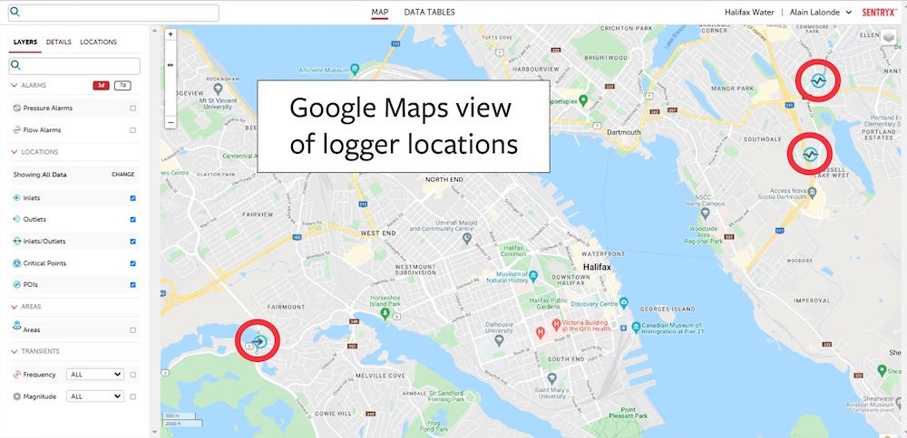
Figure 1 – Sentryx Intelligent Network Web Interface– Site Location Map View
During phase 1 of the pilot program, HW was able to derive valuable insights about its network that it did not have before and see these using the software service’s maps and graphs. Some of the most interesting insights included the detection of pressure surges and transients at one of its air valve installations as seen in figure 2. It is a standard feature of the loggers that they collect statistical data that enables transients to be detected. In addition, a routine fire flow test could easily be identified as seen in figure 3. While HW previously had pressure sensors reporting to SCADA, the i2O data loggers, by Mueller enabled the utility to monitor pressure and flow at air release valves (ARVs) and other locations without existing power and communications, without the expense of adding power or communications in an existing chamber.

Figure 2 – Pressure Surging and Transients Detected at one of the Halifax Water Air Release Valve Locations
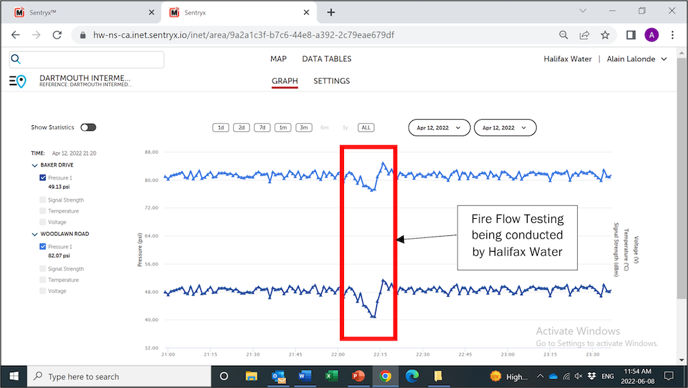
Figure 3 – Fire Flow Testing Pressure Drop Recorded at Two Separate Pressure Recorders
Phase 2 – Remote Controlled PRV
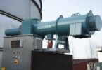
The “Zinck PRV station” seen in figure 4 has a 4” PRV main supply and 10” PRV fire flow back-up. It is the only primary feed into the Mowatt Intermediate DMA, as seen in Figure 5. The PRV was retrofitted with the Advanced Pilot Valve (APV) with the existing PRV pilot system still installed but valved off to allow for back-up control during routine maintenance. A control logger was also connected to the PRV. Utilizing the APV and control logger, the PRV can now be controlled remotely with the new advanced pressure management system.

Figure 4 – APV and Controller Installed on a 4” Singer 106-PR Pressure Reducing Valve in Halifax
The Mowatt Intermediate DMA characteristics are as follows:
- Number of connections: 479 (476 residential & 3 non-residential)
- Total length of water main: 4.0 miles (6.4 km) (mainly 8” cast iron)
- Number of fire hydrants: 37
- Number of mainline valves: 52

Figure 5 – Mowatt Intermediate DMA
As the first proof of concept to HW, the APV pilot was locally set and programmed to operate as a normal fixed outlet PRV. The current PRV pilot system on the 4” PRV was set to a constant 71 psi, and the APV was programmed to regulate the PRV output to the same 71 psi outlet pressure. Figure 6 shows how smoothly the APV unit kept the PRV outlet to 71 psi.
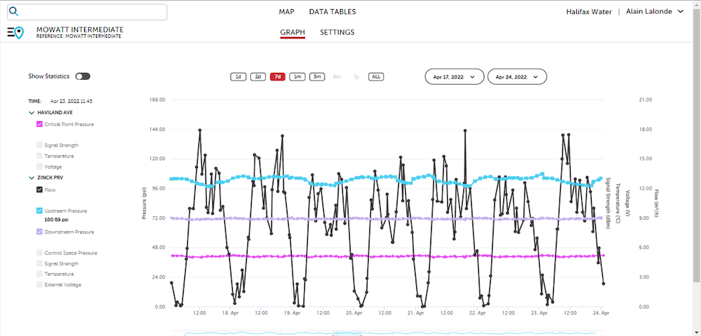
Figure 6 – Mueller APV Fixed Outlet PRV Control – Mowatt Intermediate DMA
Healy said, “I was impressed with how well the PRV outlet pressure was maintained – particularly in low-flow scenarios. The Sentryx software allowed us to change the PRV setpoint remotely and even adjust the opening/closing speeds of the PRV to offer an even smoother outlet pressure.”
Once the new pilot proved its ability to regulate and keep a constant outlet pressure, HW moved on to test control using “flow-modulation”. In flow modulation, the PRV outlet pressure is varied based on the actual demand in the DMA. This allows a lower pressure set point at night when demand is low and system head-loss is at its minimum. During peak demands, pressure is increased to overcome system head-loss and ensure sufficient pressure within the DMA. Flow modulation is ideal for lowering pressure in off-peak demands to reduce leakage flows and the occurrence of water main breaks. It also responds quickly to increase pressure at peak demands or for fire flow requirements. Figure 7 illustrates the performance of the APV pilot and pressure controller in flow modulation mode for the Mowatt Intermediate DMA.

Figure 7 – APV Flow Modulated PRV Control – Mowatt Intermediate DMA
Phase 3 – Automatically-Optimized PRV
Rather than setting fixed or timed outlet pressure from the PRV, in Automatic Optimization mode, the system takes in data from the PRV and from a logger placed deeper in the network at which the water utility wants to deliver fixed pressure levels. That position is called the “Control Point”. All the user needs to do is set the target pressure levels required at the control point by time of day and day of the week. The Sentryx Intelligent Network software service does the rest: it receives data from the PRV control logger and the Control Point logger and calculates the optimal control curve to achieve the target pressure. It then makes adjustments to the PRV outlet pressure continuously. The profile is created in the software service, then sent down to the Control Logger. It takes just 1 week to be confident in its first curve. The curve is automatically re-calculated regularly to account for changes in demand. These may be seasonal or may result from changes in customer usage in that area of the network over time (e.g., the building of new housing). The system ensures that pressures are maintained at the minimum viable level at all times. This in turn reduces leakage and the likelihood of pipe bursts. This method of optimized pressure management gives HW the highest level of security of supply while reducing NRW loss.
Figure 8 below shows how the Mowatt Intermediate DMA performed under the Optimized PRV Control Mode.
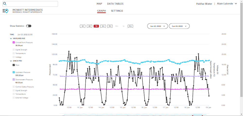
Figure 8 – Optimized PRV Control – Mowatt Intermediate DMA
Although the DMA flow profile and “night flow” for the Mowatt Intermediate zone shows that there is very little leakage in this zone, HW was still able to obtain savings from the optimized PRV control mode. Under fixed outlet control, the average daily DMA demand was 55 kGal/day (210 m3/day). In optimized PRV control mode, the daily DMA demand was 54 kGal/day (204 m3/day) – a savings of 1000 gal/day (6 m3/day) or 2.8% of the average daily demand. In a pressure zone or DMA where leakage levels are 10, 20, or even 30% the savings would be significantly higher.
Mueller’s off-the-shelf advanced pressure management solution can be installed quickly and is supported by an intuitive dashboard. Additionally, the combination of mechanical and control logic fail-safes provides the security redundancy needed for such devices.
Author: Harold Mosley, Product Engineering Manager for i2O and Hydro-Guard, Mueller Water Products


